|
As Featured in SnowTech Magazine's September 2000
Issue! By: Randy Nouis |
| Clutch tuners have always believed that the Ski-Doo TRA clutch
provided the strongest acceleration and holeshots. They also believed that once past
midrange, nothing could match the Polaris P-85. But what about backshifting? Was it really
necessary to give up excellent backshifting for good holeshots? The eternal search has
been to find the right combination to enjoy the best of both worlds. The big question has
been: Is it really possible for an aggressive upshift and good backshifting to exist in
the same clutch? For the Very first time these secrets by Randy Nouis and others are here-in revealed. But first, some
background.What
Secrets Have Ski-Doo & Polaris Kept From Us For Years?
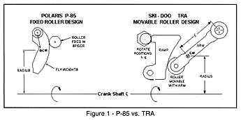
The Continuously Variable Transmission (CVT) system used in snowmobiles provides infinite tuning possibilities. In the quest to go faster, the main focus has been to improve the upshift characteristics of the CVT. But there is another side of performance, 'backshifting, which is just as important for everyone other than straight-line racers. Getting a quick upshift is pretty well understood -- using heavy aggressive clutch weights and steep helixes work well. Simply put; the more weight and helix you can pull, the faster you will accelerate. This has been the rule for many years in drag racing. But for snow-cross racing, deep snow (mountain) riding, and aggressive trail riding, back-shifting is equally as important as the upshift. Today's motors have more than twice the torque of engines produced just a few years ago, however, few motors have sufficient torque to pull hard out of a corner or up a mountain in a 1:1 shift ratio. Falling off the power peak due to the lack of backshifting leaves you behind. What is backshifting? It is a reduction in shift ratio, or down shifting. In the past, the whole issue of backshifting has always taken a backseat with most high performance people because it meant sacrificing some upshifting. But backshifting is essential for maximum acceleration in hard pulling conditions. The problem is how to achieve an aggressive upshift to hold today's high torque motors in their power band and still achieve an aggressive backshift with a single clutching setup. Several ideas have been adopted addressing the backshifting issue. The most common is to eliminate friction in both clutches. Roller primary and secondary clutches, coated helixes, and larger bearing surface clutch covers are common ways of improving backshifting qualities through friction reduction. The most popular of these methods seems to be to add a roller secondary. They improve backshifting by letting more of the torque sensing capabilities pass through the secondary clutch a pull on the primary clutch through the drive belt. But is friction the only cause of poor backshifting, or is it one of several causes? It has been my experience that fixing a problem at the source always results in a better overall system, so lets take a closer look at the entire CVT clutch system and define the "root cause" of poor backshifting. The Secondary Clutch The main function of the secondary clutch is to be a torque-sensing device. This is why many aftermarket companies build parts such as roller secondaries to improve backshifting. Being the torque-sensing device in a CVT transmission, it attempts to open the primary clutch by using the belt as a wedge to force the primary clutch sheaves apart. By moving the sheaves apart the belt can move lower into the primary. When the belt moves lower in the primary and at the same time it moves higher in the secondary, lower shift ratios are achieved (backshift). When properly calibrated, these lower shift ratios keep the motor in its power band. The Primary Clutch The primary clutch is RPM-sensing. Its main function is to apply enough belt squeezing and upshift force on the belt to hold the engine in its peak power band. The drive clutch accomplishes this by using centrifugal force generated by flyweights or arms to push the two primary clutch faces together. The rates of upshift and percent of belt slippage dictates the engine RPM. The primary clutch also has a second function that gets overlooked by most high performance clutch tuners. The drive clutch needs to respond to the pull on the belt from the secondary clutch to achieve a proper back shift. The degree of this response depends on the balance between the primary clutch spring and the flyweight. We will refer to this balance as "resolution". The force of the spring will closely match the force being generated by the flyweights when properly tuned. A well balanced system will have a high degree of resolution. "High resolution" means small pulls on the belt will more easily push the sheave halves of the primary clutch apart resulting good back shifting. The Current Problem Several things have changed in recent years that make high resolution harder to achieve. In years past, high horsepower motors were also high RPM motors, but now the industry direction is to use low RPM motors that produce more torque to create the same horsepower. To hold these high torque motors in the power band, heavy clutch weights or arms are needed. I mentioned earlier that the secondary clutch attempts to pull the primary clutch back to a lower shift ratio by using the belt. It is the centrifugal force from the clutch weights or arms that resists the pull from the secondary to backshift. Improving the efficiency or pull on the belt from the secondary clutch addresses only a small part of overall CVT backshifting. If the clutch weight or arm is too heavy, the pull on the belt from the secondary cannot override the force being generated by the clutch weights in the primary. So as engine torque increases and heavier weights are used, backshifting will diminish. One good example of how these low RPM, high torque motors effect the backshifting is the Ski-Doo Formula III 700. This single-piped triple produces phenomenal torque, and the TRA clutch is calibrated to produce sufficient upshift and belt squeezing force to hold the engine at 8000 rpm. Driving a Formula III 700 can be one of life's most exciting experiences in both acceleration and deceleration. When I first rode this machine, I let off the throttle coming into a comer. Without touching the brake, the back end of the machine became loose and started to slide. I quickly adjusted my driving style to anticipate this behavior each time I let off the throttle. I first attributed this deceleration to over tightening of the track or possibly incorrect limiter strap length. After making several adjustments, I still had the same problem. After talking to other Ski-Doo owners, I found out I wasn't alone. In fact, several of them questioned if the lack of backshifting might be the cause. After thinking about it, the theory made sense. Is the clutch arm used in the TRA clutch producing so much centrifugal force it keeps the engine connected to the track? Is the engine acting as an air brake trough the drive system, providing a "compression braking" affect? Fixed vs. Movable Roller Designs The centrifugal force produced by the flyweight or arm is the common link between the different CVT clutch designs. If we can understand how clutch design changes the amount of force applied to the belt, we may be able to increase the resolution for improved backshifting and still get an aggressive upshift. The analysis will also show why some brands accelerate harder than others at certain points on the shift curve. Today, three of the four major manufacturers have engineered their primary clutches to use the fixed roller design. The fixed roller designs include the Polaris P-85, Yamaha YXR, Arctic Cat 9 tower & Comet primary clutches. These designs incorporate the same method of using centrifugal force produced by three (or four) pivoting flyweights pushing against fixed rollers located in the spider. These flyweights are located in the movable sheave, and as engine RPM increases so does the amount of centrifugal force being generated by the flyweights. This force eventually ends up at the belt in the form of belt squeezing and upshift force. Ski-Doo opted for a different approach of providing belt squeezing and upshift force through the design of their TRA primary clutch. Top racer and those knowledgeable about CVT clutch tuning have long regarded the TRA as the best clutch for short run drag racing situations; but why? The TRA uses three arms to produce centrifugal force. Similar to the fixed roller design, centrifugal force of the three arms increases as the clutch rotates around the centerline of the crankshaft and engine RPM increases. The difference between the TRA clutch and others is that the roller, which is fixed in the other designs, is now attached to the end of the arm and the roller ramp is fixed in the spider/cover. The TRA design is referred to as a movable roller design. The two different concepts are shown in figure #1.
At a glance it appears that we have all the same parts in the fixed and movable roller design. Many people have told me that the parts for the fixed and movable roller clutch have simply been rearranged and all four primary clutches work the same. I have never found this to be true in field testing. If I put a P-85 Polaris primary clutch on a Ski-Doo, the machine feels completely different even though the shift RPM remains the same. Is it in the tuning components or is it the design that makes the two styles of clutches feel so different on the same machine? By doing some reverse engineering maybe we can determine if the fixed and movable roller designs perform differently during operation giving the machine a different feel. As mentioned earlier, all four manufacturers' primary clutches are common because centrifugal force is generated by the use of flyweights or arms. Centrifugal force calculations are the same regardless of the clutch manufacturer, the only differences are in the dimensions and the masses of the flyweights. To demonstrate how the fixed and movable roller designs work to get force on the belt, I'll use the Ski-Doo TRA and Polaris P-85 clutches as examples. Figure #1 shows how to measure the radius in calculating centrifugal force in the TRA and a Polaris P-85 clutch. Remember the radius increases as the clutch weight rotates around the stationary pin. Shown here is the equation used to calculate centrifugal force.
As you can see from this equation, three variables can be changed to produce more centrifugal force. Simply remember the following rules; 1) Increasing the mass of the weight (or arm) will increase centrifugal force. 2) Increasing the RPM of the weight (or arm) will increase centrifugal force. 3) Increasing the radius (or distance to the center of mass) will increase centrifugal force.
Shown in figure #2 are the results using this equation. This graph shows the centrifugal force (in pounds) produced as the weights rotate from clutch engagement to the full shift out position. The centrifugal force shown in Figure #2 is comparing a 67-gram arm in the TRA and a 67 gram flyweight in the P-85. All calculations are made at 8000 RPM using three weights or arms. The Ski-Doo TRA incorporates six clicker positions to fine-tune the clutch. This is a nice feature that makes a big difference to the force being applied to the belt. Our analysis shows positions 1 and 6 using the 286 ramp which is standard in the Formula III 700. Also shown in fig.#2 is the centrifugal force generated by a 60 gram Polaris flyweight. This information will be used later. Figure #2 You can see in figure #2 that as the weights and arms rotate around the stationary pins, centrifugal force increases due to the change in distance of the COM (center of mass) of the weight to the centerline of the crankshaft. If just the centrifugal force was used to determine the performance differences between the P-85 and the TRA, we would say the TRA design is more aggressive and should upshift faster than the P-85. Also note the same amount of weight (three 67 grams weights) is put in each clutch. The TRA produces more centrifugal force than does the P-85 for any given flyweight mass, due to the stationary pin location being further away from the centerline of the crankshaft. And it is centrifugal force that resists the request to downshift from the secondary. But does more centrifugal force translate to increased belt squeeze? Figure #3 shows us the amount of centrifugal force that actually makes it to the belt. Figure #3 As you can see, not all of the centrifugal force makes it to the belt. Looking at the graph you instantly realize that the TRA and P-85 have completely different force curves. Both TRA and P-85 clutches may appear similar because both use three arms (or flyweights) and a spring, but the way the force is moved through the roller to the belt clearly shows the differences between the two. The results show why a machine will feel different depending on the two different designs. You would expect that if similar rubber-compound belts are used that similar forces would be needed, but it is the differences between the fixed and movable roller designs that produces the two different force curves. The fixed roller design has limited force-producing capabilities at the lower part of the shift curve, due to the tucking of the weight under the stationary pin. In fact, only 29% of the centrifugal force produced actually makes it to the belt in the first part of the shift curve. Polaris appears to be trying to resolve this design issue. In the 2000 RMK 800, Polaris installed a wide shim between the spider and the movable sheave. This wider shim is meant to un-tuck the weight from the stationary pin and give additional force on the belt at the lower shift ratios. Even though this works, it also results in the reduction of the contact angle between the roller and weight. The overall results are an increase in force applied to the belt, but not as much as is needed. A stiffer preload spring is also necessary to keep the engagement RPM constant. Also shown in figure #3 is the TRA moveable roller design, clicker positions 1 & 6. This design produces more belt squeezing force at the lower parts of the shift curve, but has limitations in the higher part of the shift curve. This limitation is due to the fact that the contact angle between the roller and the ramp diminishes rapidly as the clutch moves to the full shift position. As little as 27 degrees of contact angle has been measured using the 286 ramp. The 27 degree contact angle between the roller and the ramp in the full shift position results in a loss of 56% of the centrifugal force produced. The same fixed roller design has a 50 degree contact angle resulting in only a 25% reduction in force. There are a number of other losses in both designs, but are not as significant as these. Other ramp profiles (flyweight curvatures) will result in changes to the force profiles shown in Figures 2 & 3, but remember that profile changes can be made to both fixed and movable roller designs. This means profile changes are equivalent for both designs. Changing profile shapes also results in a loss of force to the belt in other parts of the shift curve. The belt side force curves in figure #3 provide the tuner with some powerful information. By comparing the force curves from both fixed and movable roller designs you can understand why the TRA clutch is regarded as a good short run drag racing clutch and the P-85 is very good when top end pull is required. This also explains why Polaris tuners have such good success with multi-angle helixes; they allow the primary to upshift quickly past the low belt squeeze (inefficient power transfer) area of the clutch. But our analysis began as an effort to determine what factors in the primary clutch influence back shifting. Can aggressive up shift and good backshifting exist in the same primary clutch? If you remember in figures 2 & 3, we graphed a 60 and 67 gram weight in a P-85 clutch. The 60 gram Polaris flyweights produce three to four hundred fewer pounds of centrifugal force than the 67 gram weight. Comparing the 60 gram weight to the 67 gram TRA arms in figure #3, we see that the 60 gram weight in the fixed roller design is equal to or out performs the TRA in most shift positions; and will backshift far better. If you can produce sufficient belt squeeze with less centrifugal force, the result will be better backshifting (Less centrifugal force = better backshift). Hmmm, a lighter flyweight that backshifts better is able to generate an equal amount of belt squeeze. I mentioned earlier the trend in the industry is to use low RPM high torque motors, and the centrifugal force equation points us to the basic problem. By using the equation we see that lower engine RPM's will produce less centrifugal force than a higher revving engine, but we need more belt squeezing force to stop the belt from slipping due to the increased torque of the motor. This seemingly leaves us with only two options to increase the force needed - increase the mass of the flyweight or arm or increase the distance from the centerline of the crankshaft to the center on mass. But as we have seen, you do not necessarily have to increase the centrifugal force to increase the belt squeeze. The answer? While building an entirely new clutch would be ideal (and expensive), it may be possible to produce the desired results with some simple re-arrangement and adaptation of newly developed components. These new components for the TRA clutch have been tested over the past season, and may quickly become the 'must-have" system for competitive racing. Already approved by ISR, they will be given the ultimate test - race- track performance. We have made every attempt to lead you right up to the "door", but you'll have to open the door yourself and walk in. The Heel Clicker( clutch weights will work with any clutch kit you may already have. Remember the dual quadrant deign simply fixes a flaw in the CVT clutch design, and will only compliment any other clutch kits on the market. The Heel Clicker( clutch kit comes with two high preload clutch springs (specially designed to utilize the advantages generated by the cam weights), weights, and all the necessary adjustable hardware. You may also wish to read: "Inside Clutch Tuning:
The "Heel Clicker" Flyweights were featured in the September 2000 issue of SnowTech Magazine.
To order yours or learn more, visit our website at or
|


)
)