Inside Clutch Tuning:
Tune the Primary or the Secondary?
As we all know, clutching is a very complicated subject. In fact, some
people will tell you it’s simply a “Black Art” that takes years to
understand. As an engineer I always look for evidence that supports a complete theory of
clutching. What has always worked for me is using computer simulation to give direction in
which way a mechanical system will behave. Often, simply removing preconceived notions
from my way of thinking can result in true knowledge gained. This has been my experience
many times, what I thought was true, was not! When you have an end result in mind before
you start a project you rarely come up with the right answer. Always ask yourself,
“how does the system fit together, how does one component react with the other
component in the system?
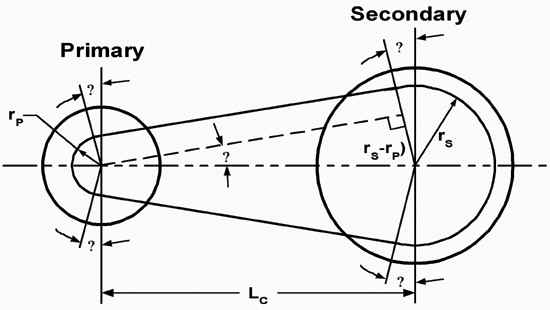
Figure 1
Clutching is one of those high emotional areas of snowmobiling. Pipes and
porting also draw lively conversation, and I think its all for the same reason. Most high
performance snowmobiles want to go fast. As fast as the limitations of the engine size
will let them. There is nothing like getting your 600cc sled to out run an 800 in a 660
ft. drag race. That’s bragging rights.
This article deals with one of the most asked questions in all of high performance
snowmobiling. Savvy tuners realize that working with several different clutching
components can give similar end results on the tachometer. For example, putting in lighter
flyweights gives similar results on the tachometer as putting in a shallower helix. But
one set-up is faster than the other, so is just reading the tach the right answer? Which
clutch should I work on, and why? These are some of the most asked questions in all high
performance snowmobiling.
This article uses computer simulation to try to answer some of those questions. Many man
hours of programming and engineering are represented in the following pages. A
“Static” analysis is the first step in understanding what the system needs to
basically work.
Low CVT Efficiency Leads to Slow Acceleration
The CVT clutch system is one of those brilliant but simple devices that manufactures,
purchasing agents, and engineers like to see. It is simple to assemble, cheap to build,
and it is very efficient in power transfer when properly calibrated. Chances are they will
be around for a while.
Overall CVT clutch efficiency is based on several major factors, but as we will see tuners
have control over just a few of them. Listed below are the “built in” areas of
efficiency loss. These losses are due to engineering compromises that always occur when
designing an entire power train package. High performance customers and engineers alike do
not like the word “compromise”, but it’s a fact of life. Product cost,
standardization in tooling, and environmental issues are all things that have to be
considered when designing any product.
In a CVT transmission, standardization in tooling seams to be the driving force of many
engineering decisions. All four major snowmobile manufacturers use the same clutch on a
variety of different machines. For example, Polaris uses its P-85 clutch on 35 hp 340cc
fan cooled machines all the way up to the XCR 800 making 160 hp. Polaris makes many
different tuning components such as springs (primary and secondary), flyweights, helixes,
gears, and shims, but that’s not what we are talking about. It is the fixed variables
(an oxymoron) that are basically cast into the design. Things like center hub diameter,
sheave face angles, outside diameters, contact patch area, and material choices. These are
just a few major design considerations that greatly affect CVT clutch efficiency.
Designing a CVT clutch system around 35hp@7200 rpm instead of 160hp@8500 rpm will result
in a lot of compromises. All manufacturers have this same problem; how to achieve the best
overall performance for a variety of different engines and sled designs.
These above mentioned areas of CVT clutch design are basically fixed by each manufacturer.
Some of these design choices are impossible to change and would require a complete
redesign and retooling of the clutch itself.
Contact Patch
The contact patch area between the belt and the sheave face is the easiest but most
critical function to understand. It is a physical measurement of degrees of contact
between the belt and the sheave faces multiplied by the thickness of the belt. The cross
sectional area of the belt is constant and does not change, but the contact angle between
the belt and sheave face (both drive and driven) does. This changing contact patch between
the belt and the sheave faces is the most critical area of clutch tuning to understand. It
is this changing contact patch that requires the CVT clutch system to continually change
the amount of force being applied to the belt from both the drive and the driven clutch.
Belt stretch above transferring the torque of the engine will result in a drop In CVT
drive efficiency. The results will be lower track horsepower.
The schematic diagram and data provided in Figure #1is very powerful and shows how the
contact patch changes during shift out for both the primary and secondary clutches. Ten
equally spaced shift ratios from 3.8:1 (low ratio), and 0.8:1 (over drive) are shown. The
degrees of contact between the sheave faces and belt are calculated by using SAE standard
formulas at the belt pitch diameter. Since the belt is a constant length, as the shift
ratio increases the belt contact angle between the primary clutch and belt also increases,
and conversely the contact angle in the secondary clutch decreases.
(click for...)
Figure 2
Belt Contact Angle vs. Shift Ratio
Also notice the rate of contact angle gain (in the primary) and lose (in
the secondary) is not linear. In other words, the degrees of contact between the belt and
the sheaves change much more rapidly as we approach the 1:1 shift ratio. The rate of
angular contact appears to be linear up to the 1.84:1 shift ratio then it changes
drastically. This should be your first clue that a straight angled helix is not the
optimum solution to achieving maximum CVT clutch efficiency.
The most important data in figure #1 is that the primary clutch has less contact patch
area then the secondary clutch until the 1:1 shift ratio. This means if you have poor
acceleration and mid range pull, the primary clutch is more than likely the proper clutch
to be working on because slippage is more likely to occur due to the smaller contact patch
in that clutch.
If you are searching for more top speed, the secondary clutch should be altered for the
same reason. Installing a less aggressive helix, a stiffer secondary spring or changing
gear ratios will increase side force on the belt preventing the belt from slipping due to
the rapidly decreasing contact patch area in that clutch.
Understanding Helix Angles
In the secondary clutch, a helix /spring combination is used to generate belt squeezing
and up shifting forces. Helixes and secondary springs are calibrated to balance the pull
from the belt created by engine torque plus the up shift force generated by the primary
clutch at a point where the engine will shift out at a constant rpm.
The secondary clutch works off a torque feedback mechanism that senses load at the track
through the chain case. This torque feedback mechanism is a very clever device that has
been a challenge to simulate.
Just like the primary clutch, belt squeezing forces are the “axial” forces
created by the sheave angle. (Caution: Do not confuse the sheave angle with the helix
angle.) Squeezing force is the force that stops the belt from slipping due to changes in
engine torque and the changing contact angle during shift out.
Up shifting forces are also refer to as “belt pinch” by many old timers in the
business. Belt pinch provides the “balance” between the primary and secondary
clutches. It is the radial forces created by the sheave angle. Belt pinch is created in
both primary and secondary clutches, but instead acting in the same direction they oppose
each other. This opposition of forces makes the CVT clutch sensitive to load changes.
(click for...)
Figure 3
Helix Radius re: Button/Roller Contact Point
As we have shown in the past, most primary clutch sheave angles are
between 24-28 total degrees depending on the manufacturer. In the secondary clutch total
sheave angles as low as 19 degrees have been measured. Why don’t some secondary
sheave angles match the primary clutch? There may be good reasons.
Secondary clutches produce belt squeezing and belt pinch forces through the use of a
helix/spring mechanism. The helix is the primary component in the secondary clutch that
develops these forces. A secondary spring is used as a fine tuning device, and in most
cases the magnitude of a spring change is small compared to the helix (but not all cases).
To simplify the following information, helix force data is shown only. Spring data is
fairly easy to obtain and comprehend.
Figure #3 shows a simple helix diagram. Notice all calculations are taken at the
button/roller contact point.
Axial displacement, angular displacement, and helix radius are all major design features
used to calculate forces of different helixes. Axial, and angular displacement is taken at
the point of first to last contact between the button/roller and helix angle.
(click for...)
Figure 4
Belt Force vs. Shift Ratio
Using a Yamaha helix and the SRX 700 power curve as an example, Figure #4
shows how much belt squeeze, and up shift force is produced at 90 ft-lb of engine torque,
100 % traction with several different helix angles.
As you can see, changing the helix angle from 40-52.5 degrees will drop the belt squeezing
force from 1414.5 to 918.2 lbs. at the 3.8 shift ratio. A 35% decrease in squeezing force.
Up shift force also drops the same percentage. Also notice at full shift (.8:1 ratio)
there is very little between the different angled helixes. This is a key piece of tuning
information that you will use in the up coming example. All four major manufactures
helixes act the same way but use different helix radiuses. Arctic Cat and Yamaha use about
the same 45mm radius, Where Ski-Doo and Polaris use about a 40mm radius.
The data in figure #4 shows that you will see big differences in belt squeezing and up
shift forces at low shift ratios, but don’t expect big differences at the full shift
out point.
You can also build a helix with this data; just connect a start point to an end point. A
compound 50-40 helix will yield the same results.
Putting it all together
Last year we showed how different primary clutches (Ski-Doo TRA& Polaris P-85) worked.
They have two different mechanisms that provide force to the belt in different ways. The
analysis shown in this article provides information on how the secondary clutch works.
Comparisons can how be made at different shift points.
The common denominator between the primary and the secondary clutch is the belt. It acts
as a link between the two clutches and all it sees are pulling and squeezing forces. The
belt is the key component of the entire CVT clutch system. As we mentioned earlier low CVT
efficiency will result in low track horsepower. Belt slippage and belt stretch are the two
functions that must be controlled though proper calibration.
Each manufacturer has it own standards of calibrating CVT clutching. Calibration is
dictated by engine power, machine and driver weight, and traction just to name a few.
(click for...)
Figure 5
Belt Force on Drive & Driven
In the example below we will examine a clutching set up for the Yamaha SRX
700. For this analysis a 45 degree helix was used instead of the standard 47 degree, and a
53 gram weight is shown instead of the 51 standard weight.
Figure #5 puts both the primary and secondary clutch on the same page. It compares both
belt squeezing and up shift forces at equally spaced shift points. To fully understand the
power of this information I have added a few notes to the graph.
In the circle (start of up shift point) the graph shows the two up shift curves crossing.
This means with our calibration, over rev. off the bottom will occur. Notice the analysis
is run at 8500 rpm, and 90 ft-lbs of torque. The primary clutch has not generated enough
up shift force to over come the up shift force in the secondary. The two up shift points
should be the same before the clutches will start to shift out. This problem can be solved
by two different methods. Adding more clutch weight to increase the up shift force in the
primary, or by putting in a less aggressive helix in the secondary.
The second point of interest is the fact that the primary and secondary clutches have
different shaped up shift curves. Notice the spread between the curves is greatest at the
0.4 inch point, and degrades all the way to the full shift out. This means we will have
harder up shift in the midrange than we do at full shift out. Always remember the greater
the differential between these two lines will result in faster acceleration as long as the
motor can pull it.
The up shift lines are extremely important. The up shift from the primary clutch must
always exceed that of the secondary clutch or the CVT clutch system will stop shifting
out!
I talked earlier about belt stretch and belt slippage being forms of efficiency loss. Up
shift force in the primary and the secondary are built in losses in the CVT clutch design.
At the midrange point 310lbs of pull from the primary clutch is added to 180lbs of pull
from the Secondary clutch. This then added to the pull on the belt due to the engine
torque of approx. 800lbs at that shift point. A total of 1290lbs pull force on the belt,
but only 800lbs due to power transfer.
The last point of interest is shown at the 1.0 inch displacement point. Belt squeezing is
the most fundamental function of the CVT clutch system. Without sufficient belt squeeze
there is no torque transfer. At the 1 inch /600 lbf point I place a box. At this point we
should expect similar belt squeezing in both the primary and secondary clutches. Remember
our discussion on how the contact patch changes as the clutches shift out. At this point
the contact patch area is the same for both clutches, so similar belt squeezing forces are
needed. The amount of force needed to stop the belt from slipping changes based on
different factors. Belt compounds, sheave heat due to slippage, amount of traction all
effect the force needed to stop the belt from slipping. Based on this target, the graph
shows the Primary clutch has sufficient force to stop the belt from slipping, but
that’s not the case with the Secondary clutch. It appears that this helix/spring
combination does not apply enough force to stop the belt from slipping. A shallower Helix
and a stiffer spring are needed.
Summary
Figure #5 contains good information. It shows the different functions of the entire system
and how they relate to each other. By examining Figure #5 you can understand why this
article was named as it was. In this example, increasing the belt squeezing force with a
shallower helix and stiffer secondary spring will stop the belt from slipping in the
secondary clutch, but also increased the up shift force. There was simply nothing we could
do about it because the up shift force is fixed to the belt squeezing force through the
sheave angle. This is one of those fixed variables we talked about earlier set by the
manufacturers. Remember the 19-degree Secondary sheave angle we talked about earlier? You
figure it out.
By trying to fix one problem, we created another. The difference between the up shift
forces in the primary and secondary were already coming together at full shift out. Adding
the shallower helix and stiffer secondary spring to solve the slippage problem, also
creates the potential of actually stopping the clutching from fully shifting out because
now the up shift force in the primary starts to match the up shift in the secondary!
Solving this problem lies in the primary clutch. Even though there is sufficient belt
squeezing force in the primary clutch at the 1:1 shift ratio, additional up shifting force
is needed to offset the increase up shift force due to the shallower helix angle and
stiffer secondary spring. Adding more clutch weight or decreasing the top spring load are
the two ways to increase primary up shift force. In most cases clutch weight is the right
answer, because it takes very little weight to add several hundred pounds of load to the
belt.
This was a real world example of a 2001 SRX 700 in our test fleet. By adding 63 total
grams of dual quadrant clutch weight, and a 48-36 helix. The system worked as predicted.
No over rev off the bottom, hard midrange pull and excellent top speed numbers.
You may also wish to read:
"Inside Clutch Tuning:
"HC-X" Roller Secondary System"
The "HC- X" Driven Clutch Kits were featured in the
December 2001 issue of SnowTech
Magazine.
 Authorized
Distributor. Authorized
Distributor.
(Dealer inquiries welcome.)
To reserve yours or learn more,
visit our website at
www.sledgear.com
|


)
)
)
)