|
As Featured in SnowTech Magazine's
November 2003
Issue! By: Randy Nouis |
||||||||||||||||||||||||||||||||||||||||||||||||||||||||||||
Inside Clutch Tuning:
In designing a CVT primary clutch there are several key components that can be changed to effect calibration. These components have individual functions that produce the proper upshift and belt squeezing forces to match the engine power curve. Achieving maximum track horsepower throughout the shift curve is the goal of the tuner. It has been my experience this is best achieved by working in the primary clutch. In primary clutch design, the "Force Split Function" and the "Center Of Mass (COM)" location of the clutch weights have the greatest influence on upshift & belt squeezing forces. These two functions are separate but are directly connected by the COM location of the clutch weight. To fully understand how the tuner can use this information, a full explanation of the two functions is needed. The force split function is when the centrifugal force generated by the clutch weights gets split, or divided, between the roller and stationary pin. In other words, not all of the centrifugal force generated by the flyweights is applied to the rollers and squeezes the belt. The force distributed between the pin and the roller is not equal and changes as the clutch shifts out. The force split must be calculated at each shift point. The stationary pin and roller are fixed locations in the CVT primary clutch. The function of the stationary pin and roller is to hold the clutch weights in place so the weights do not come out of the clutch as the clutch rotates. The most difficult part of understanding the force split function is determining what the distances are that are used in the calculation. This is why the location of the COM point becomes critical. Belt Forces
The COM (center of mass) point is the balance point of the clutch weight. Half the mass of the clutch weight is on one end, half on the other. To demonstrate what the COM point looks like figure #1 is shown. In figure #1, the Polaris 10-60 flyweight is used as our example weight. The other two weights are the same 10-60, but with 5 grams moved to the base and then the tip from the center. By visually looking at the profile, the COM can be located for each. It is the balance point. As you can see in figure #1 these three different weights that all weigh 60 grams have different COM points because of their different "profile" or shapes. One has a heavy tip, one a heavy base, and a "standard" 10-60. The resulting upshift and belt squeezing force curves for both weights are also shown. The force curves are different for each weight. The heavy base weight produces an additional 150lbs on the bottom but 100lbs less on top than the modified 10-60 with the heavier tip weight. What figure #1 demonstrates is one of the agonies of clutching. How to get a complete solution? How can we achieve hard upshifting on the bottom and the midrange while maintaining hard upshifting on the top without the overall weight being too heavy? This issue is common with all OEM style clutch weights regardless of brand. There is nothing we can do with a standard clutch weight to fix the problem of throwing hard on the bottom and on top with the same weight. Standard profile adjustable and nonadjustable weights can only push the problem to another location on the shift curve.
(click for...)
The dimensional differences in the location of the COM in figure #1 seem insignificant at this point, and many inexperienced tuners lose interest because of the small dimensional differences. This is where paying attention to magnitudes starts to pay off. One or two millimeters is a very small distance when the clutch weight is on the workbench, but once they are put into the clutch, the differences will become apparent. The COM point of the clutch weight must be carefully measured to achieve reliable data. To help understand how important the COM location is and how it affects both the force split function and the centrifugal force; a schematic diagram is shown in figure #2 Shown in figure #2 are five rotational positions of the same Polaris 10-60 clutch weight use dimensions used to calculate force split and centrifugal force. Both are calculated at the COM point of the clutch weight. This means if the COM of the weight is moved, both force split and centrifugal force will change. The following equation is a simple way of looking at how the force split function works. For the engineering purist, summing of the forces is the proper way. But this gives us the same results and is much easier to understand. Force (lb) = A x Centrifuged Force (Roller) L Force split is basically a percentage. It tells us where the centrifugal force is going. To balance the equation, the centrifugal force generated by the weights has to go to the stationary pin or the roller; there are no other choices. As you can see in figure#2, when the roller moves away from the stationary pin, both dimension (A) and (L) increase. But they do so at different rates causing the centrifugal force transferred to the roller to diminish. As stated earlier, the remainder of the centrifugal force goes to the stationary pin. At the stationary pin location, the pin and bushing are round thus none of the centrifugal force can be turned and used to produce upshift and belt squeezing forces. Centrifugal force is generated by the clutch weights, and is always calculated at the same COM point of the weight to the centerline of the clutch. The equation for centrifugal force is as follows. Centrifugal Force (lb) = 0. 18 x (0.838 x R) 2(8000 RPM, 60 grams) R x 0.004448 As we saw earlier, the COM location is hard to measure because of the complex shape of the clutch weight. In standard shaped OEM or Aftermarket clutch weights, the COM is generally located between 18-23mm from the center of the stationary pin. By examining figure#2, you can quickly figure out why the COM point is so critical in the design of the clutch weight. The COM location effects both the centrifugal force equation and the force split equation. So both equations have to be used together to get a complete look at the overall results. This is where most tuners fall short in their analysis. They simply don't realize that both equations have to be used to get the overall picture. As an example, our 10-60 Polaris clutch weight has a COM point at 21.18min from the center of the stationary pin. For a OEM style weight, it is considered to be a heavy base weight and will accelerate hard because the COM point is located further away from the centerline of the clutch in then the heavy tip weight also shown in figure #1. Both the radius and velocity terms in the centrifugal force equation are effected by any movement of the COM point. By having the COM point further away from the centerline of the clutch, more centrifugal force is generated by the clutch weights. Belt squeezing and upshift forces are increased on the bottom end. At the full shift out point (position#5) of the same 10-60 weight the COM point is closer to the stationary pin than the roller. When calculating the force split equation the percentage of force going to the roller falls off drastically. This means slower upshifting on the top end.
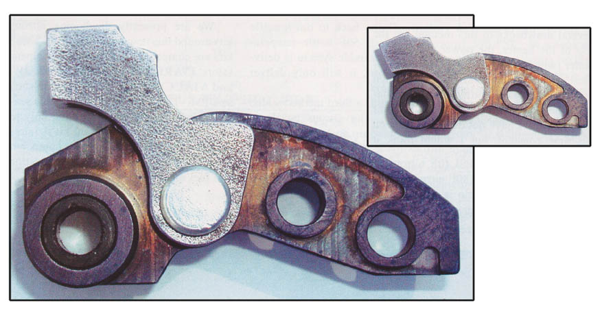
A clutch weight of the same mass and profile 10-60 (Heavy Tip) shown in figure #1 has a COM 22.53mm away from the stationary pin and will not accelerate as hard because the COM point is closer to the centerline of the clutch at position #1. The radius term is smaller meaning the velocity will also be smaller, and the result will be less centrifugal force. As we have shown, the problem with a standard profile (adjustable or non-adjustable) clutch weight is obvious. The tuner can only push the problem around. Since the COM point is tied to both the centrifugal force equation and the force split equation one equation will always increase, while the other will always decrease during weight rotation. The tuner can only fix one part of the shift curve with a standard profile clutch weight. The physics of achieving both hard acceleration and good top end speed with a standard OEM shaped clutch weight is simply not in the cards. The force split equation and the fixed COM point of the clutch weight makes it impossible to achieve both. Fixing the problem The solution is to separate the force split equation, and centrifugal force equation from the COM point. By examining figure #2 we see that the centerline of the clutch, stationary pin location, and roller location are all fixed points in the clutch design. These three points are used in the calculation of the centrifugal force and the force split but are built in at the factory and simply can not be changed. The only point that can be changed is the COM location. But, as we have seen, changing the COM point only moves the problem around and really solves nothing. You still end up with major compromises in some part of the shift curve. So we need to devise a way of moving the COM point at the right time to optimize overall performance.Increasing one of or both the values of "R" or "A" in position #1 will give us a heavy base weight needed for hard upshifting on the bottom and middle part of the shift curve. By increasing "R" the amount of centrifugal force will be greater, and by increasing dimension "A" more of it will end up at the roller location. The same is true at position #5; if values "R" and "A" increase, more centrifugal force will be generated and a higher percentage of that force will go to the roller. That will create hard upshift on the later part of the shift curve. What has changed between positions #1 to position #5 is the rotation of the clutch weight itself. The weight has rotated roughly 90 degrees around the stationary pin. This is why the problems can only be moved around. What helps in position #1 works against you at position #5 every time! The opposite is also true. If we could move the COM point at the right time, we can create a weight that upshifts hard on both the bottom end of the shift curve and top end. If we could move the COM point of the clutch weight as it rotates without changing the overall weight we would have a complete solution! Getting the COM point of the clutch weight to move requires a two-part flyweight body. The main body must have a cam surface for the roller to ride on. And the other section (referred to as the shoulder) is simply movable weight attached to the main body. Shown in figure #3 is an example of such a clutch weight. It is referred to as a "Dual Pivot Point Clutch Weight". In this example the weight is comprised of a 40 gram body and a separate 20 gram shoulder weight (60 grams total). This will allow us to compare it to the Polaris 10-60 shown earlier. The two separate sections of the weight are connected with a second rotational pin. The second pin locks the two separate sections together so they can act as one weight. The second pin location is critical to the design. The second pin location will dictate at what point the shoulder weight becomes independent and starts acting like tip weight. This design works because centrifugal force always throws radially. When the second pin location lines up with the shoulder weight, the shoulder weight decouples from the body of the weight. As figure #3 shows, rotation of the main body around the stationary pin is used to our advantage to decouple the two parts. Clutch weight rotation gives us a method of moving 20 grams from the base location to the tip location so the weight can be aggressive at the right time.
(click for...)
(click for...)
To get a complete solution, no other function should be adversely affected. This movement of the shoulder weight should not affect any other function except to move the COM point of the assembly forward during shift out. This weight will act as a heavy base and then a heavy tip weight at just the right time. Also shown in figure #3 is a force curve comparing the Polaris 10-60 with our Dual Pivot Point 40-20. Both weights are the same 60 total grams. The force curve shows that the movement of the 20 grams of weight physically moves the COM point further from the stationary pin location. The results shown in figure #3 demonstrate how effective the Dual pivot point weight is. In this example, the Dual Pivot Weight is shown as a 40-20 weight split, but a 42-18 would completely flatten the force curve. Also notice the point where the two force curves meet, the shoulder decouples from the body at this point. Backshifting of the Dual Pivot Point weight will be greatly improved over conventional OEM style weights. OEM style weights distribute the mass along the length of the clutch weight. In this example, the Dual Pivot weight has 20 grams positioned at the second rotational pinpoint only. By placing the second rotational pin closer to the stationary pin, we get the positive upshift effect of a heavy tip as the weight rotates without paying the penalty on the backshift. This is due to the fact that no weight was added forward of the second pin location. This design does not distribute the weight forward to the tip as an OEM style weight. In future designs weight distributions of 50-50 body and shoulder will be common. Summary As we have shown, a standard style weight lacks the geometry to achieve maximum upshift on both the bottom end and the top end of the shift curve. In the current weight design, the tuner can move mass from one end of the clutch weight to the other. But this results in moving the problem from one part of the shift curve to another. A physical solution of achieving maximum upshift throughout the entire shift curve has been shown. Moving the COM point while the weight is rotating around the stationary pin places the COM point at the proper place at the proper time. The "Dual Pivot Point Weight" creates a constant rate of shift for a complete solution. Many different combinations of base weights and shoulder weights can be tailored to match the power curve of all 2 & 4Stroke engines. In this example we showed a 40-20 gram split between the body and shoulder. But 30-30 splits may also be used. By moving the COM point, backshifting capabilities are greatly improved due to the minimum amount of tip and total weight needed to hold the engine in its power band. Remember, the shoulder weight is used twice during shift out. This makes the weight smarter, not heavier.
The "2-Speed" Dual Pivot Clutch Kits were featured in the November 2003 issue of SnowTech Magazine. You may also wish to read:
To reserve yours or learn more, visit our website at
|
||||||||||||||||||||||||||||||||||||||||||||||||||||||||||||

)
)
)
)