You've most likely heard of and understand
"backshifting" when it comes to snowmobile belt transmissions, but what
about "downshifting"? Wouldn't it be a desirable thing to, at will,
downshift the transmission much like a car or truck? A "Passing Gear"? Can't
be done, you say?
For performance snowmobiles, clutching is an area of great performance
gains. Using sound engineering techniques, we have identified weak areas in
the performance of the CVT clutch system, and presented solutions in
numerous Snow Tech articles.
When doing advanced work in any technical field sometimes you get unexpected
results that advance technology in areas you didn't expect. In other words
you're getting answers to questions you didn't ask. It's scary to think you
didn't totally understand what you were doing, but just got lucky. I like to
use the old adage "the harder you work the luckier you become".
A savvy Clutch tuner and friend Joel Snyder from Albany, MN, made me take a
step back and reevaluate CVT secondary clutch systems and the way they work.
His theory was based on what he was seeing from a new product on the market
named the Heel-X. You may have seen it briefly advertised late last year.
The goal for the Heel-X is to create a helix that up shifts very
aggressively by moving the leverage points in the secondary clutch. More on
how the system works later.
After having a "spirited" conversation with Joel about how it was impossible
for a CVT transmission to work the way he described it, I decided to go back
and reevaluate what Joel was seeing in the field. I was surprised to find
Out we were both right; we were just asking two different questions. What I
wanted was maximum upshifting and back shifting in one design. Joel told me
as he pushed the throttle on his 1010 Arctic Cat, he observed the belt
moving LIP the secondary sheave before it started to up shift. In other
words, the belt was briefly moving in the wrong direction.
Joel told me that the harder he pushed on the throttle, the further the belt
moved in the wrong direction before it started up shifting. The result was
extremely hard up shifting because every time he pushed the throttle the
clutches moved to a lower gear ratio resulting in immediate peak horsepower
rpm. I told him, "Wow, what a concept if it could only be done". Well, he
was right; welcome to the world of "Down shifting"!
What is Downshifting?
Downshifting is a common function of an automatic transmission built for
automotive use. All car and truck drivers experience downshifting when
making passing maneuvers or pulling heavy loads up hills. Cars and trucks
with automatic transmissions and even snowmobiles are calibrated to over
shift or run at rpms lower than maximum torque and horsepower at cruising
speed. It's not uncommon to see only 1500 rpm at 75 MPH while driving my
Suburban. Over shifting allows engines to run at lower rpm where motors live
longer and achieve higher fuel mileage. Over shifting is great for fuel
mileage and engine durability, but what about performance? As a snowmobiler
how many times have you seen 50mph while the tach reads 5000 rpm, and you're
hardly pushing on the throttle? This is classic over shift and every brand
and model of snowmobile experiences it. Downshifting is the function that
solves over-shifting in automatic transmissions.
For automotive use, when more power is needed for passing maneuvers the
engine rpms are raised and the gear ratio is lowered. Engine rpms are
directly tied to a gear ratio change. This changing of gears is referred to
as downshifting. For the driver, downshifting is accomplished by simply
pushing on the throttle. By pushing the throttle the automobile senses
changes in the intake manifold pressure and throttle position. At
pre-determined set points in the calibration of the automobile's software,
it recognizes the changes in throttle position and manifold pressure. The
software then sends a signal to the transmission to shift to a lower gear
ratio which makes it very easy for the engine to reach an rpm where maximum
power is produced. Snowmobiles have not had downshift capability like our
cars. To make a rapid passing maneuver, the driver had to rely on engine
horsepower only. If we wanted more pulling power and acceleration we just
traded up to a bigger sled with more torque.
Downshifting accomplishes the same goal as increasing engine torque. It uses
gear ratio changes, not air and fuel for more acceleration. Equipped with
downshifting even small displacement machines can accelerate and feel like
much larger sleds.
Downshifting also gives the driver the ability to put more power to the
ground "before" the driver gets to the obstacle. At the base of a hill or
from a hard packed road to an open field of powder, maneuvering around
obstacles while hillclimbing, the driver can downshift into a lower gear
ratio before he gets there.
As we will see over shifting at part throttle conditions is common. It's
part of the current CVT Clutch design, and it can't be fixed. Since file
primary clutch uses centrifugal force to generate belt squeezing and up
shift forces, and the secondary clutch uses torque input to generate belt
squeezing and up shift forces they do not respond the same way to less than
wide open throttle (WOT) conditions.
Downshifting vs. Backshifting
It's important to understand the difference between back shifting and
downshifting. They sound like they should work the same
way, but they are totally two different functions. Back shifting and
downshifting have the same goal; to move the belt to lower gear ratios, but
they accomplish this function in two completely different ways. With back
shifting the driver has to wait until the CVT drive system senses a load
change and then the system will shift to lower gear ratios allowing the
engine to remain at peak power rpms. With downshifting, load changes do not
have to be encountered before the driver can initiate a gear ratio change.
With a downshifting CVT clutch system, differences in loading conditions are
not important.
From an engineering viewpoint the powerful concept of downshifting lies in
the fact that the driver finally has the control of the making gear ratio
changes just like our cars. For our high performance snowmobilers, the
biggest advantage of downshifting, is that a sled will pull like it has a
larger engine. Remember, sleds without downshifting strictly have to rely on
horsepower to overcome over shift. With downshifting you will have
horsepower and gear ratio working to accelerate the machine. Savvy clutch
tuners will quickly realize that downshifting will allow them use much more
aggressive clutching set-ups without sacrificing back shifting. Maximum
track horsepower setups can now be used for mountain use and snowcross.
(click for...)
Figure 1
Belt Forces-Drive & Driven
How the CVT Works
To explain how CVT clutch systems work a graphical representation is shown
below in Figure #1. This Figure is a stock calibration curve for a stock
ZR800. A similar graph was shown last year in the fall issue of Snow Tech
for an SRX 700. This figure shows the belt squeezing and up shift force of
both primary and secondary clutch for a ZR 800. Belt squeezing force in both
the primary and secondary clutch is pretty well understood. If you don't
squeeze the belt hard enough, it will slip creating heat and result in power
loses to the track. (See Figure 1) But it is the up shift part of the graph
that will help us understand downshifting and back shifting. Remember when
looking at the primary and secondary up shift curves, they are pulling in
opposite directions. We snow them in our graph as being positive numbers,
but they radically push in opposite directions.
High performance drag racing snowmobilers are concerned about wide open
throttle (WOT) conditions only. But WOT conditions are seen less seldom
compared to other driving conditions. Remember to get to full shift out you
have to go through every other shift point. This is why the OEMs calibrate
for "drivability" not maximum power transfer. Most of their customers use
their machines in driving conditions similar to Snowcross, Hill cross,
Hillclimb and Boon docking The driver is in and out of the throttle
constantly making part throttle conditions the most important area to tune.
As we will see it's these part throttle conditions that cause over shifting
of the secondary clutch.
I mentioned earlier that over shifting is common in all snowmobile brands
and models that cannot be fixed using current CVT designs. It's important to
understand how the CVT Clutch system works that causes over shifting to
occur. If we identify why the system over shifts maybe we can figure out a
way of work around it without fixing it.
What Causes Over Shifting?
Over shifting is a built-in design flaw in the CVT clutch system. I know
these are powerful words, but in a low cost, static power transfer system
compromises have to be made. CVT systems from every manufacture use the same
principles of an RPM sensing primary clutch and a torque sensing secondary
clutch connected by a drive belt.
Even though the system has its flaws, the current CVT system is an amazing
device. Its low production cost, ease of assembly, and efficient power
transfer make it a very competitive transmission compared to other designs,
so some flaws are tolerated. As customers we will see these types of
transmissions around for many years.
The design flaw I'm referring to is the fact we have a torque sensing
secondary clutch with an engine that varies in torque output. As we will see
the engine can vary in torque output by 40% depending on the throttle
position. So how do you calibrate the primary and secondary Clutch at
anything less than wide open throttle (WOT) conditions and expect it to
work'? You don t, it's something we have to work around.
Let's take it closer look at the design of the torque secondary clutch,
varying engine torque, and rpm sensing primary clutch design to understand
the problem.
(click for...)
Figure 2
Engine Performance
Varying Torque and the Primary Clutch
Up shift force in the primary clutch is achieved by rotating flyweights
around the centerline of the Clutch. Depending on the mass and the location
of the flyweights. Centrifugal force is generated. This centrifugal force is
then used to push the sheave halves together forcing the belt up the sheave
faces. A spring is used to counter act the centrifugal force until a
predetermined rpm is reached. This allows the motor to come up to an rpm
where sufficient engine horsepower is produced to move the snowmobile
forward. The spring actual subtracts force in the primary clutch. You would
think anything that subtracts centrifugal force from getting to the belt
would be a detriment and it is. That's why high preload, and soft end load
springs are popular.
The primary Clutch has one major shortcoming that contributes to over
shifting. The primary clutch senses rpm not power. At any rpm regardless of'
power output, the Clutch weights produce the same amount of centrifugal
force. Since the Clutch weights sense rpm only they do not know whether the
operator is at WOT or any partial open throttle condition. The ZR 800 will
be used for our example in this article. In Figure #2, a graph is shown of
the engine torque curve for the ZR 800 at different throttle settings.
Engines have the ability to make different power levels. As the operator you
have control of the amount of air/fuel entering the engine. A basic rule of
engine design is that less air input means less torque and less horsepower.
By pushing on the throttle you are simply controlling the airflow into the
engine. More air flow = more torque.
As you can see at WOT peak torque is 100 ft-lbs torque at 7400 rpm. At 6000
rpm torque is 83 ft-lbs. If we now look at 25% part throttle conditions the
same engine makes only 60 % of the torque it made at WOT. At part throttle
an engine capable of making 83ft-lbs of torque @ 6000 rpm now only makes 50
ft-lbs.
Engines have the ability to make different power at the same rpm. This
causes the OEM's to calibrate for the worst case conditions or WOT. They
have no other choice it' they would calibrate at any other throttle
condition than WOT the engine Would simply over-rev
at peak power.
(click for...)
Figure 3
Upshift Force - Primary
To hold the rpm at 7500 rpm (peak horsepower) three 70.2 gram clutch weights
are used in the ZR800. In figure #3 we show the up shift force produced at
different engine rpms. Three 70.2 grain clutch weights are mounted into an
Arctco nine tower clutch.
As I stated earlier, the clutch weight is rpm sensing only. As rpms change,
so does the centrifugal force produced by the clutch weights. Engine torque
is not a variable used when calculating centrifugal force. This means the
70.2 gram clutch weights needed to hold the engine at 7500 rpm produce way
more centrifugal force than needed at part throttle conditions and this
contributes to over shifting
While the clutch weights produce more force than needed at part throttle
conditions, there is nothing you can do about it. If the tuner wants maximum
power transfer you have to hold the engine at peak engine horsepower at WOT
conditions. Some clutch tuners recommend going to a lighter clutch weight to
stop over shifting. But aggressive clutch weights are the single biggest
gain in track horsepower gain. As soon as you lighten the weight, power
transfer falls off. Lets not forget that maximum power transfer is the goal.
Pulling the belt Lip the primary sheaves is the biggest gain in track
horsepower of any single clutch tuning component.
The major hurdle in solving over shifting is in the secondary clutch. The
secondary senses partial engine torque at part throttle conditions. So as
soon as less than maximum torque is seen at the secondary clutch, it's LIP
shift force drops. This allows the secondary to over shift because there is
insufficient leverage on the helix to stop it from up shifting.
(click for...)
Figure 4
Constant Radius Helix
Secondary Clutch Design
Secondary clutches are divided into two separate functions: a torque sensing
function and a force dividing function.
The torque sensing function is based oil leverage or distance from the
location of the belt to the touchpoint between the helix and button/roller
location. A roller or button can be used for this example. Friction is not
taken into account just the distance from the center of the clutch to the
roller/button.
First we have to understand the secondary Clutch and how it takes engine
torque and turns it into force at the helix by using leverage. In figure #4
a schematic diagram of the current technology Arctic Cat secondary clutch.
All manufactures' secondary clutches work the same way; the distances are
different.
The secondary Clutch strictly works off of torque input. To do the analysis
we have to turn engine torque into belt pulling force. The belt pulling
force (F) is always changing because the gear ratio is changing. As the belt
climbs in the primary clutch it also falls in the secondary clutch. As you
can see in figure #4, at the 3.8 shift ratio (SR) the pitch radius (PR) is
5.362 inches and at full shift out .8 shift ratio 3.008 inches.
All calculations are made at the "belt pitch radius (PR)" for both the
primary and secondary clutch. The belt pitch radius is where all the
distance calculations are made to convert torque to force.
(click for...)
Table 1
Constant Radius Helix
Torque is simply force times distance, so by knowing what the engine torque
is we can calculate a belt Pull force. Figure #4 also shows a table of how
the belt pull force changes as the clutches shift from a 3.8 to .8 shift
ratio. Table #4 shows that at any shift ratio the belt pulling force and
pitch radius are decreasing, while the distance to the roller/button touch
point remains constant at 1.772. You can also see that the force at the
roller/button touch point (FR) also decreases. But look at the leverage we
talked about earlier. . At the 3.8 (SR), belt poll (F) due to engine torque
was 850.4 lbs. Through distance or leverage it ends Lip as 2572 lbs. at the
roller/button touchpoint.
To understand over shifting in the secondary clutch, you have to understand
figure #4. It shows that small changes in engine torque will significantly
reduce the force feed into the helix. This is due to the larger leverage
action built into the secondary clutch.
Two other forces are pulling on the belt. They are the belt pinch forces
shown earlier. These forces are shown in figure #1 created by the primary
clutch and the secondary clutch. The two pinching forces pull in opposite
directions and create balance between the primary and secondary. From figure
#1 at the 3.8 shift ratio 350lbs of pinch force is generated. The primary
produces 100 lbs and 250 lbs is produced in the secondary both pulling in
opposite directions.
****NOTE *****
For this analysis the up shift force will not be added to the belt pulling
force caused by engine torque. This is a demonstration only on how the
secondary clutch works and absolute numbers are not important. It is
important to know they are there. In fact when designing belts, pulling
force on the belt due to the up shift force accounts for 40% in some cases.
Up to this point we have just looked at the leverage portion of the
secondary Clutch design. You can see how powerful force times distance can
be. That's why putting a cheater bar on a wrench works.
Fine tuning the force at the roller (FR) and turning it from a radial motion
to a linear motion is the function of the "Helix". The helix attaches the
stationary and movable sheave halves at the (FR) touch point location. The
helix radially locks the two sheave halves together and based on its angle
and diameter produces side force (SF). The side force is then divided based
oil sheave angle into belt squeezing and up shift forces.
(click for...)
Figure 5
Constant Radius Helix
In figure #5 there is a diagram of how 35, 45, 55 degree helixes work. For
all you Trigonometry fans this is the fun part. The belt is touching both
the stationary and movable sheaves, so the force between the roller/helix
(FR) and the helix/stationary (FB) sheave are the same. The formula for side
force (SF) is also given.
To calculate side force, just plug in the numbers. I have also shown how to
calculate the angle. It's simply the tangent of rise over the run. The
tangent value becomes very important later in understanding back shifting.
I like to show the equation of how things work. By understanding that we
gain a full knowledge of what call be changed and what has to be left
constant. In the case of the secondary clutch to change side force (SR) the
variables (F), (SR), and (PR) call not be changed easily. These variables
are built in at the factory, and would have to be designed in. But in the
case of (RR) distance to the touch point between the roller/button and
helix, and Tangent angle, these variables both reside in the helix and can
be changed easily.
True understanding of mechanical devices is understanding what the tradeoffs
are. In the case of the helix two variables can be changed. The angle and
the distance to the touch point will both give you changes to the overall
side force, but at what price'? We will see what the difference between
these two variables very soon. We have been accustomed to changing the angle
for many years, but what have we lost in the process?
(click for...)
Figure 6
Shift Forces - Secondary
In Figure #6 we final combine the torque sensing and force dividing
functions to create an entire secondary clutch. The same three helixes are
compared to determine the difference in up shift force. Straight 35, 45, 55
degree helixes are shown. An Arctic Cat red/white spring has been installed
for this analysis, and sheave angles are a combined 28 degrees.
As you can see the 55 degree helix produces 241 lbs. of up shift force at
the 3.8 shift ratio. The 45 degree helix produces 339 lbs. at the same 3.8
shift ratio; ant the 35 degree produces 479 lbs. Upshift force falls as the
secondary shifts out regardless of what helix you use. You can easily see
how this happens in the leverage part of the clutch design. As the belt
starts to drop, the leverage distance also drops (look at PR). This drop in
leverage is a big problem in the current design that needs to be fixed.
In the past the only why to increase or decrease side force to the belt was
to change helix angle (or spring). This is shown as an option in the side
force equation. This is the why multi-angle helixes are popular.
By changing helixes from a 35 to a 55 degree, the primary clutch would see
238 tbs. less up shift force to overcome in the secondary clutch. This
allows the belt to fall faster and result in quicker up shift.
As shown a 55 degree helix produces 238 lbs. less force to overcome on the
up shift, but it also means 238 tbs. less on the backshift.
As a rule of thumb in a secondary clutch what helps on the up shift will
also hurt you on the backshift. Steep helixes, soft springs, less rotational
twist are one way functions. They allow for good up shift but poor
backshift. This is why tuners are always searching for the "magic helix and
spring combination". A combination that will beat his buddies on race road,
and to race road.
Up to now we have looked at the secondary clutch design with 100 Ft-lbs of
engine torque (WOT). We saw how the secondary clutch is designed to use
leverage to magnify engine torque or belt pull (F) and produce a force at
the helix (FR). The force is then fed into the helix and up shift force is
produced based on the helix angle, diameter, and sheave angle.
What happens at less than WOT conditions? Remember the OEMs have calibrated
for WOT conditions; they simply have no other choice. At WOT the ZR800
produces a maximum of 100ft-lbs of torque, but at part throttle the engine
produces as little as 50 ftlbs. From our analysis, if the torque input
changes, so does the up shift force. So at part throttle conditions up shift
force will fall.
In our example of engine torque shown in figure#3, Engine torque varies
widely. Figure #7 shows the up shift force curve when using data shown in
figure #3.
As shown in figure #7, when less than 100 ft-lbs of torque is seen at the
secondary clutch, belt pinching or up shift forces also go down due to the
fact the basic component (pull on the belt IF)) has been reduced.
System Over Shift
To pull all this information together we just have to compare three of the
figures shown.
Remember the ZR 800 engine shown in figure #2; it has the ability to vary
the torque widely based on air flow at different throttle settings. At 6000
rpm the ZR 800 can produce torque between 83-50 ft-lbs based on how much air
is fed into the engine by different throttle settings.
The engine sends this varying amount of torque to the primary clutch shown
in Figure #3. The primary clutch is rpm sensitive only. The primary clutch
is not designed to detect torque changes, so when it sees 6000 rpm, it
produces 185 lbs. of up shift force regardless of engine torque. This 185
lbs is a fixed number and cannot change unless the rpm changes.
(click for...)
Figure 7
Shift Forces - Secondary
The secondary clutch is torque sensing so any changes in torque Output Will
change the up shift force applied to the belt. In figure #7, you can see at
83ft-lbs of torque (WOT), 185lbs. of up shift force can be produced by the
secondary clutch. This will balance with the primary clutch and stop the
primary clutch from over shifting. Unfortunately, this only happens at
maximum torque output. Data on Figure #7 shows that any less torque input to
the secondary results in insufficient up shift force to balance with the up
shift force of the primary clutch. In this figure no other engine torque
value can pull hard enough to produce the 185 lbs of up shift force needed
in the secondary to stop the primary clutch from continuing to shift. The
result of this is over shifting.
What is the System Flaw?
Over shifting is a fact of life. It happens in all CVT clutch systems and
cannot be eliminated. The root cause of over shifting is the secondary
clutch's inability to stop the primary clutch from pulling it into a higher
shift ratio. We can work around this flaw by separating some key variables
and optimizing them independently to minimize the over shift condition.
To solve problems like this you have to create a system where you can change
what needs fixing and make it invisible to the rest of the system. The helix
combines several different functions that need to be separated.
To build a downshifting secondary clutch, we have to separate the up shift
function from the backshift function. We have to invent a system that
removes the "mechanical impedance" while maintaining an aggressive up shift.
A downshift is a point where the up shift in the secondary is higher than in
the primary clutch. This will cause the belt to move in the opposite
direction only if the mechanical resistance or impedance is removed.
Mechanical impedance is a choke point to the system. It can be a benefit or
a detriment to a system depending on what the goal is. Electrical engineers
and technicians use electrical impedance all the time. It's the slowing down
or speeding up the flow of electrons at some point in a circuit. For
mechanical engineers, impedance is measured by the resistance to movement.
To understand mechanical impedance in the secondary clutch, the tuner needs
to understand just one number. That number is the tangent angle shown in
figure#5.
In trigonometry, the tangent function value is an interesting number, but
can easily be understood. In figure #5, the tangent of 45 degrees is 1. That
means that the length of the two axis (rise and run) are the same. But
drastic things happen soon after you go over or under 45 degrees. In figure
#5 we also show a 35 and 55 degree helix. The 55 degree helix is shown
because this is the approximate helix angle (55/53 stock) used to calibrate
the ZR800 from the factory. This helix along with a red/white secondary
spring makes up the secondary calibration of the ZR 800.
Shown below are the tangents of the three helixes.
Tangent(35) = 0.7 Tangent(45) = 1.0 Tangent(55) = 1.43
For mechanical devices the tangent value is directly related to mechanical
impedance. The higher the tangent value is, the higher the impedance. As you
can see these small changes in helix angle mean big changes in the ability
of the secondary to backshift.
So going from a 35 degree helix to a 55 degree helix increases the
mechanical impedance by 100%!
Small helix angle changes make huge impedance changes. We have all
experienced how steep helixes will not backshift--now you know why.
Aftermarket companies and the OEMs have been trying to reduce friction in
the secondary clutch for years. Rollers, harder buttons, bigger bushings,
coated helixes--these are all ways to reduce friction. These methods all
work to some degree. I remember when roller secondary clutches first came
out; they removed rolling resistance between the button and the helix.
Everyone scrambled to know what helix to run to achieve an equivalent rpm as
their old button clutch. The answer turned out to be four degrees. If you
had a 40 degree helix in a button clutch you now used a 36 degree with a
roller secondary. Rollers were a great improvement to the secondary clutch.
And you could feel the improved response with just 4 degrees of helix
removed (remember) the tangent function). Rollers did not work because they
removed friction, they worked because the reduced friction allowed the tuner
to run a shallower helix resulting in less mechanical impedance.
All of the friction reducing devices I mentioned earlier simply work by
allowing the tuner to shallow out the helix and reduce mechanical impedance.
Now imagine a device that goes right to the problem and solves mechanical
impedance directly! A device so the tuner can remove 20 degrees of helix or
more and achieve the same up shift! What's that going to feel like?
(click for...)
Table 2
Decreasing Radius Helix (HC-X)
How to separate up shifting from back shifting and create downshifting
To understand how to get rid of 20 degrees or more of helix angle, we just
need to understand the side force equation seen in figure#5.
I briefly touched on this earlier that the helix is the only changeable
component that can accomplish the task of separating the up shift from the
downshift. The side force equation in fig.#5 basically shows the only two
variables that can be changed are the tangent angle, and the distance (RR)
from the center of the shaft to the roller/button to helix touch point. Both
these variables are in the denominator of the side force equation, so by
increasing one and decreasing the other the side force can go unaffected.
(click for...)
Figure 8
Decreasing Radius Helix (HC-X)
Increasing helix diameter allows us to remove helix angle.
It's purely by luck that the angle and the distance (RR) are both situated
in the helix. The helix is already the most changed component in the
secondary so very little training for the tuner is needed.
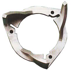
As I mentioned earlier the Heel-X uses a new technology referred to as
"decreasing radius technology." This new technology uses a wide roller so as
the secondary shifts out the touch point between the roller and the helix
moves inward. This allows the distance to the touch point between the
roller/button (RR) and helix to change as the belt pitch radius (PR) changes
(See figure #8). In this figure, the same data is shown as in fig.#5 except
the (RR) has changed. You can see the force fed into the helix (FR) is
reduced at the 3.8 (SR) by 21% And at the 0.8 (SR) the force is increased by
12%. This means the total side force is lowered for a very fast up shift
with and no belt slippage on the top end!
Changing the radius touch point feature in the helix "decouples" the up
shifting function from the back shifting function allowing optimization of
both. You simply eliminate the mechanical impedance by reducing the helix
angle. We get back the rapid up shifting by angle. We get back the rapid up
shifting by changing the leverage points or distances (RR).
(click for...)
Figure 9
Secondary - Shift Forces - Helix Comparison
This new decreasing radius technology is very powerful. In figure #9, a
graph is shown of the up shift force produced by the standard 55 degree
helix. This helix is used to calibrate the ZR 800 shown in figure #1.
Remember the up shift force must be sufficient to stop the engine from
overreving at WOT conditions. That's why steeper helixes are used for bigger
engines. In figure #9, 1 have engineered two helixes that are exact matches
to the 55 degree Arctic Cat helix. These two helixes, a 35 and 45 straight
cut have the exact same up shift force as the 55 degree helix. The
touchpoints have been moved to remove leverage to compensate. These helixes
remove large amounts of mechanical impedance without sacrificing the
aggressive up shift characteristics.
In new designs, looking for the downside of a design is always a priority.
If we gain in one area, do we lose in another'? What are the compromises?
Besides the possible weight difference of the larger helix, there is no
significant downside to this helix design.
This tech article started out by discussing downshifting and we quickly got
into secondary clutch design. By understanding the design we know what to
fix and what to leave alone. But downshifting is a function that you get for
free from a good design (lucky). It's always been there, but we couldn't get
to it.
To achieve a downshift, the up shift force produced by the secondary clutch
must be higher than the up shift force produced by the primary clutch. This
will allow the belt to be pulled in the opposite direction creating the
downshift function. If you look at Figure #1, I put a circle around the area
where this occurs, and this point can be moved. What prevents downshifting
is mechanical impedance. When the up shift force in the secondary is higher
than the primary, downshifting can occur. But the up shift force has to be
high enough to over come both the mechanical
The decreasing radius helix technology solves the problem of mechanical
impedance. It separates the up shift function from the backshift function
and allows the downshift function to actually work.
The "HC-X" Driven Clutch Kits were featured in the
September 2002 issue of SnowTech
Magazine.
You may also wish to read:
"Tune the Primary or the Secondary?"
(How the primary & secondary clutches
interact)
Tech for Arctic
Cat, Comet, Polaris & Yamaha clutches.
(How Heel Clickers work)
Tech for Ski Doo TRA clutches.
(How TRA Heel Clickers work)
Tech for External Roller Type Secondary clutches.
(How the "HC-X" works)
 Authorized Distributor. Authorized Distributor.
(Dealer inquiries welcome.)
To
order yours or learn more, visit our website at
www.sledgear.com
|

)
)
)
)
)
)
)
)
)
)
)